Why Vacuum Environment Changes the Rules—and How SANYO DENKI Delivers
A vacuum chamber is unforgiving: no convective cooling, no wayward air molecules, no second chances when a component fails 200 km above Earth. Traditional rotary feedthroughs still work, but they hog footprint, add leak paths, and throttle speed. Drop the motor inside the envelope—provided it’s engineered for vacuum—and your mechanism shrinks, simplifies, and stays repeatable for the long haul.
Below is a practical guide to vacuum levels, common applications, failure modes, and how the SANMOTION vacuum‑rated motor—especially the stepper family—mitigates each of them.
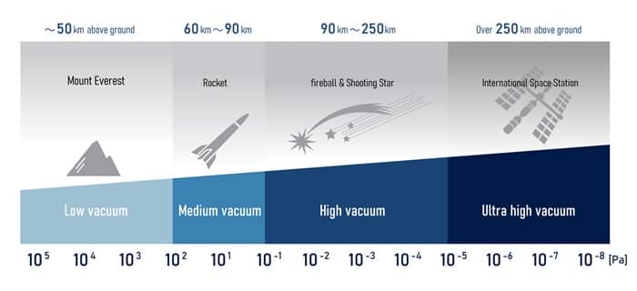
1. How “Vacuum” Is Your Vacuum?

|
JIS Classification |
Common North American Term |
Pressure (Pa) |
Pressure (Torr)* |
Typical Uses |
|
Low Vacuum (低真空) |
Rough / Low Vacuum |
10⁵ → 10² |
7.5×10² → 7.5×10⁻¹ (≈ 750 → 0.75) |
Food/medical packaging, CRTs |
|
Medium Vacuum (中真空) |
Medium / Fine Vacuum |
10² → 10⁻¹ |
7.5×10⁻¹ → 7.5×10⁻⁴ (≈ 0.75 → 0.00075) |
PVD, etch, solar cell tooling |
|
High Vacuum (高真空) |
High Vacuum |
10⁻¹ → 10⁻⁵ |
7.5×10⁻⁴ → 7.5×10⁻⁸ |
Electron microscopes, lasers |
|
Ultra High Vacuum (超高真空) |
UHV |
< 10⁻⁵ |
< 7.5×10⁻⁸ |
Synchrotrons, space hardware |
|
— (Not in JIS) |
Extreme High Vacuum (XHV) |
< 1.3×10⁻¹⁰ |
< 1×10⁻¹² |
Fundamental physics R&D |
* 1 Torr = 133.322 Pa.
2. Why Put the Motor Inside the Chamber?
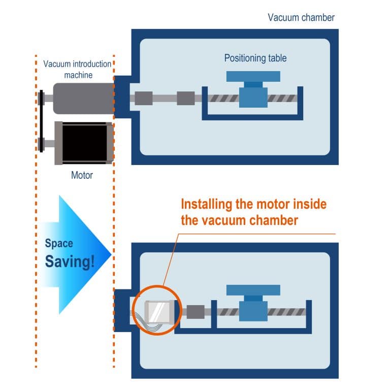
Installing a vacuum‑rated motor directly inside the chamber removes the bulky rotary feed‑through—and with it, several longstanding drawbacks. Engineers often see:
- Space Savings – Eliminate bulky rotary feed‑throughs.
- Higher Precision – No wind‑up or backlash from long shafts or bellows.
- Cleanliness – Fewer seals means fewer leak points and less particle shed.
- Throughput – Faster index times without atmospheric re‑pressurization cycles.

3. Where Vacuum Rated Motors Are Used
3.1 Earth Based Manufacturing
- Semiconductor & Flat‑Panel Lines – Wafer handling, mask stages, load locks.
- Metallurgical & Additive Furnaces – Crucible tilt, build‑plate Z‑axes.
- Surface‑Science Tools – Sample carousels in XPS/SEM/TEM.
3.2 Spacecraft & Orbital Platforms

Across satellites and spacecraft, motors actuate a wide range of critical mechanisms.
- Robotic Arms
Motors drive multi‑joint arms that remotely grab, release, and manipulate objects outside the spacecraft. - Communication Antennas
Satellite and spacecraft antennas are motor‑positioned to stay correctly pointed at Earth (or another craft) so links stay locked. - Solar Arrays
Array‑drive motors rotate panels toward the Sun to capture maximum light and keep power flowing. - Thrusters / Nozzle Gimbals
Motors steer or actuate thruster nozzles. When the nozzle moves, high‑pressure gas is expelled in a controlled direction, generating the thrust needed to change orbit or speed. - Reaction Wheels
A cluster of motor‑spun wheels handles fine attitude and orbital tweaks. Speeding up or slowing down a wheel imparts the counter‑rotation needed to point the spacecraft precisely where it needs to look.
These are only a few examples. Motors underpin spacecraft and satellite operations, delivering precise motion and staying reliable in harsh conditions—mission success depends on them.
5. Failure Modes in Vacuum—And SANMOTION Countermeasures
Here’s how vacuum stresses motors—and how SANMOTION counters each failure mode.
|
Engineering Pitfall |
The Vacuum Effect |
SANMOTION Design Tactics |
|
Thermal Run‑Up |
No air → resistive losses stay in windings |
200 °C‑rated insulation; loss‑minimised copper fill |
|
Outgassing |
Oils/solvents evaporate, contaminate optics & pumps |
Zero rust‑preventive oil; pre‑bake + solvent‑free clean; vacuum grease or solid‑lubed bearings |
|
Porous Castings |
Die‑cast parts trap bubbles → gas release |
Flange & end‑bracket fully machined from billet aluminum |
|
Differential Expansion |
Mixed CTE distorts stator stack |
Matched‑CTE materials keep micron‑level alignment |
|
Inefficiency = Heat |
Every wasted watt becomes radiant heat load |
Optimized magnetic circuit drops I²R & core loss |
6. Specification of the SANMOTION Vacuum Stepper Motor

Motor Sizes:
42 mm (NEMA 17) 2- and 5-Phases
56 mm (NEMA 23) 2- and 5-Phases
60-86 mm 2-Phase
Key Features
- Direct‑vacuum operation—no feed‑through required
- Sub‑arc‑second positioning with 5‑phase drive
- Up to 200 °C tolerance
- Radiation‑tolerant builds for nuclear or orbital duty
- Fully RoHS‑compliant materials list
- Can be used up to UHV environment.

7. Customization Without Compromise
The vacuum usage environment varies from customer to customer.
At SANYO DENKI, we can provide a wide range of customizations to meet your needs.
Examples:
|
Application |
Custom Work |
|
Wafer‑inspection stages |
Low‑outgassing, Kapton‑lead harness |
|
ISS Robotic Arm Prototype |
Complete redesign: solid lubrication, 1×10⁻⁷ Pa qualification |
|
Electron‑Beam Deposition |
Integrated planetary gearbox, 10⁻⁴ Pa |
|
Nuclear‑Fuel Handling |
Radiation‑shielded windings & connectors |
|
LCD Sputtering Tools |
Hollow‑shaft geared motor with UHV bakeability |
Need a hybrid that isn’t on the datasheet? We machine, wind, vacuum‑bake, and assemble in‑house—iterating until the motor matches your load, pressure, and duty cycle. Contact our expert today.
If you’d like to know about SANMOTION Stepper Motor, read: Precision Made Simple: High-Accuracy Positioning with Stepper Motors
Request A Consultation
Request a consultation for your customization needs. Our team will be in contact with you soon to provide further information and answer any questions you may have.
